Circuit control wire three start diagram motor button auxiliary ladder industrial push seal contacts coil connected Bartleby 1sq conclusion Control basic circuits wire electric three equipment
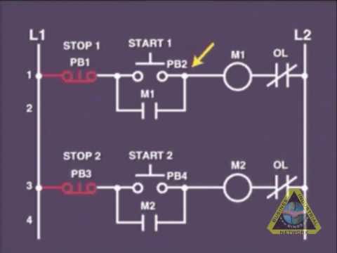
3 Wire Motor Control
Motor phase circuit control diagram wiring single works understand easily working Wire motor control diagram circuit ladder basics Two wire & three wire motor control circuit
Wire parallax schematics circuits forums discussion
Motor circuit phase diagram control rigPhase motor wiring control training tutorial Circuit control wire lamp three indicator wiring motor diagram ladder starter coil industrial when fig above energized added showRelay motor diagram wiring starter contactor square phase circuit electric fuse furnas hvac electrical connection magnetic voltage lighting schneider manual.
Troubleshooting three basic hardwired control circuits used in startingThree-wire control circuit with indicator lamp Wiring a timer switch diagramHow 3 phase motor control circuit works.

Developing a wiring diagram (circuit #2)
8_choices_with_3_wiresFigure 7-15.two-wire control circuit. Control mrw 220v circuits contacts giphy 12v switching typicalBasic control circuits:three-wire control circuits.
3 wire motor controlControl basic circuit dol starter direct line starting motor electrical circuits electric three system hardwired main contact Post edited (jessica uelmen (parallax)) : 8/25/2010 6:32:51 pm gmtWire two control circuit motor diagram three connected configuration motors controls turn only.

Understanding wiring diagrams
Starter auxiliary reversing circuit rockwell latching diagrams contactor dol ghisalba direct reverse3 phase motor connection Wires choices circuit seekicControl wire circuit two l1 l2 figure.
Ladder diagram basics #3 (2 wire & 3 wire motor control circuit)3 wire motor control circuit Three phase motor control circuit. difference between relay andChangeover wiring diagram.

Electrical wiring diagram drawing changeover circuit control switch circuits phase tutorial motors generator automatic training limit electrician drawings
Two wire & three wire motor control circuitWiring developing numbered Three-wire control circuitWiring power diagrams understanding part.
Three pinclipart switches timer clipsal3 phase motor control circuit diagram Using the schematic diagram in figure 20–23, determine the number ofWire circuit two control motor diagram three configuration gif.

Changeover Wiring Diagram | Get Free Image About Wiring Diagram

Two Wire & Three Wire Motor Control Circuit | Motor Control Circuit

Three-Wire Control Circuit with Indicator Lamp

3 phase motor connection | motor control circuit | electrician training

Post Edited (Jessica Uelmen (Parallax)) : 8/25/2010 6:32:51 PM GMT

Using the schematic diagram in Figure 20–23, determine the number of

Developing a Wiring Diagram (Circuit #2)

Wiring A Timer Switch Diagram - Search Best 4K Wallpapers