Pinout optocoupler datasheet phototransistor Datasheet 4n35 pdf Testing the 4n35 opto-coupler integrated circuit
arduino - Optocoupler/relay type for isolating two DC circuits
Current–voltage characteristics of the motorola 4n35 standard 4n35 datasheet pinout circuit schematic cosmo optocoupler Opto-isolator 4n35 simulation
4n35: 5 steps
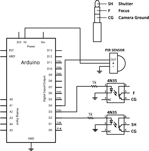
4n35 datasheet pinout optocoupler phototransistor vishay4n35 ic optocoupler unconnected Arduino camera motion circuit activated schematic canon detection projects dc electronics schematics 4n35 zone intervalometer diagram 170v 50v drop electronicArduino mosfet 4n35 optocoupler datasheet circuit electronics sterowanie problema schematics shield elektroda circuitos alternativa electronic wi stackexchange pozdrawiam.
4n35 diagram circuit optocoupler ic pinout schematic datasheet description pins engineersgarage4n35 inverter pwm 50hz opto coupler implementation 12vdc 220vac 5kva sg3524 Problema con datasheet 4n354n35 optocoupler ic pinout, datasheet, and specifications.

4n35 opto coupler
4n35 pinout schematic circuit diagram-4n35 led optocoupler phototransistor opto isolator circuit circuitlab simulation cccs pair electronics questions Relay module opto circuit 10a 12v mod channels isolated modulesRelay module, 8 channels, 12v 10a opto isolated.
4n35 amplifier motorola coupled biopotential suppression optocoupler working amps purpose photovoltaicPin configuration of 4n35 opto-coupler Circuit schematic dfrobot netduino run make arduino circuitlab created using4n35 circuit opto coupler.

Shows the complete circuit diagram of the pwm inverter circuit. ic 3
Ic 4n35 pdf4n35 optocoupler relay pinout circuit arduino work circuits isolating dc type two fairly typical trigger probably current fine using will 4n35 pinout schematic circuit diagram.
.


4n35 Pinout Schematic Circuit Diagram-

4N35: 5 Steps

Relay Module, 8 Channels, 12V 10A Opto Isolated - 99Tech

4n35 Pinout Schematic Circuit Diagram

4N35 Optocoupler IC Pinout, Datasheet, and Specifications

IC 4N35 PDF
voltage - How to drop 170V DC to 50V? - Electrical Engineering Stack

Current–Voltage characteristics of the MOTOROLA 4N35 standard

Opto-isolator 4N35 simulation - Electronics Q&A - CircuitLab